A machining operation can be highly accurate, the cutting tool can be correctly selected, and the CNC program can be perfect.
But there is still one basic question that must be answered:
Is the workpiece located correctly?
If a component shifts, tilts or sits differently each time it is loaded, even a capable manufacturing process can produce inconsistent results.
This is where the 3-2-1 principle of location becomes important.
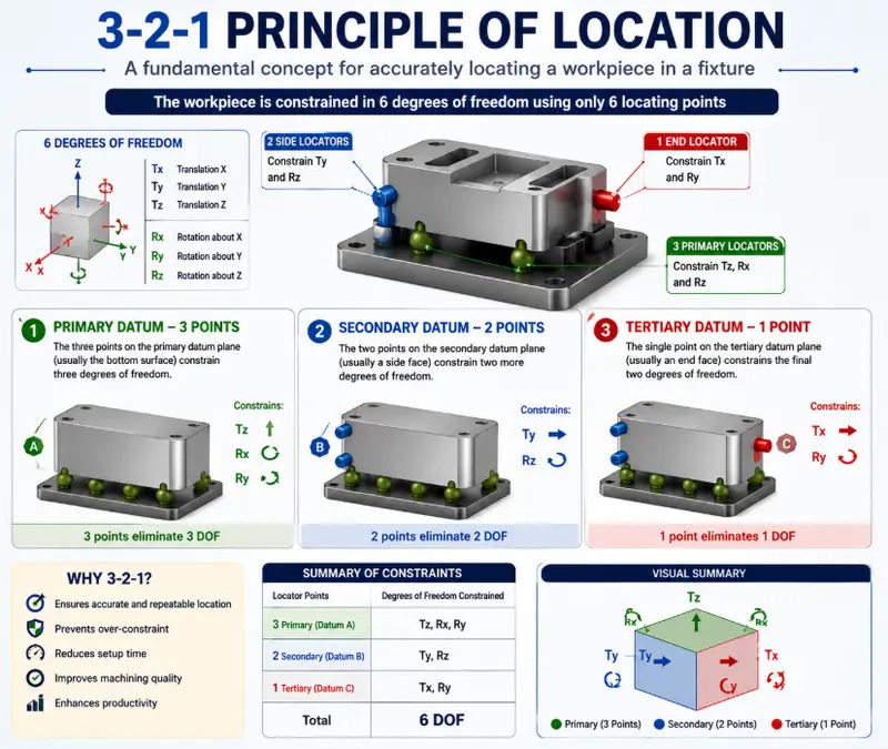
It is one of the fundamental concepts used in fixture design and workpiece location to establish a repeatable position before machining or inspection.
The idea is simple:
3 locating points.
2 locating points.
1 locating point.
Together, they establish the workpiece against three mutually perpendicular reference surfaces.
But the engineering behind those six points is worth understanding.
What Is the 3-2-1 Principle of Location?
Think of a component placed freely in space.
A rigid body has six degrees of freedom:
- Translation along X
- Translation along Y
- Translation along Z
- Rotation about X
- Rotation about Y
- Rotation about Z
The purpose of a fixture is not simply to “hold” the component.
It must establish a known and repeatable location for that component.
The 3-2-1 locating principle achieves this using three sets of locating points placed against three reference surfaces.
3 points → Primary location
2 points → Secondary location
1 point → Tertiary location
The result is a stable and repeatable workpiece location.
NPTEL’s fixture-design material similarly describes locating a workpiece against three adjacent surfaces using 3, 2 and 1 locating pins and emphasizes that locating should be easy, quick and accurate.
Step 1: Primary Datum — 3 Locating Points
Imagine placing a rectangular component on a fixture plate.
The first three locating points support its primary surface.
Why three?
Because three non-collinear points establish a plane.
This primary locating surface provides the foundation for the workpiece position.
In a typical setup, it prevents movement normal to the primary plane and controls rotations associated with that plane.
There is also a practical design lesson here:
A stable fixture starts with a stable primary location.
NPTEL specifically notes that a minimum of three points should be used to locate a horizontal flat surface and that locating pins should be positioned as far apart as feasible.
Step 2: Secondary Datum — 2 Locating Points
The workpiece now has a stable primary reference.
But it can still move in other directions.
Two additional locating points are therefore placed against a second surface, normally perpendicular to the primary reference.
These establish the secondary location.
They further orient the component and prevent unwanted movement relative to the second reference surface.
Now the workpiece is much more tightly defined in space.
Step 3: Tertiary Datum — 1 Locating Point
One degree of positional freedom still needs to be established.
A final locating point contacts the third reference surface.
This is the tertiary location.
The workpiece now has a defined position relative to all three reference surfaces.
The concept can therefore be remembered simply as:
3 points establish the primary reference.
2 points establish the secondary reference.
1 point establishes the tertiary reference.
Locating Is Not the Same as Clamping
This distinction is important.
A locator establishes where the workpiece should be.
A clamp keeps it there.
These functions should not be confused.
A well-designed fixture first establishes the correct location and then applies appropriate clamping so that the component remains seated against its locators during the operation.
That difference sounds simple, but it is fundamental to good fixture design.
Why Does the 3-2-1 Principle Matter?
Consider two components machined one after another.
The machine program is identical.
The tool is identical.
The dimensions on the drawing are identical.
But if the second workpiece sits differently in the fixture, the machining result can also be different.
A repeatable locating system helps reduce this variation.
That can contribute to:
Better repeatability
Each component starts from a consistent reference position.
Improved machining accuracy
Features can be produced relative to known locating surfaces.
Reliable inspection
Inspection results become more meaningful when parts are consistently referenced.
Reduced setup errors
Operators have clearly defined locating points.
Better process consistency
Production becomes less dependent on judgement during every loading cycle.
Where Is the 3-2-1 Principle Used?
The principle is particularly relevant to:
Machining Fixtures
Components need a reliable position before milling, drilling, boring and other operations.
Jigs and Fixtures
Locating elements establish the component’s position while the fixture or jig supports the manufacturing process.
Inspection Fixtures
Parts need repeatable referencing during dimensional inspection.
CMM Inspection
The broader concept of establishing a datum reference framework is central to dimensional measurement and GD&T. ASME’s GD&T training specifically covers datum reference frames, six degrees of freedom, datum precedence and constraining degrees of freedom.
Production Engineering
When hundreds or thousands of components are manufactured, repeatability becomes just as important as achieving the correct dimension once.
3-2-1 Location and GD&T: Are They the Same?
Not exactly.
This is an important distinction for anyone learning mechanical design.
The 3-2-1 locating principle is commonly used to explain physical workpiece location in fixtures.
GD&T datum reference frames provide a formal engineering framework for establishing references from which geometric requirements are defined and evaluated.
They are closely related ideas, but they should not simply be treated as interchangeable terms.
ASME Y14.5 explicitly deals with datum references and degrees of freedom as part of geometric dimensioning and tolerancing.
Understanding both helps an engineer connect:
Design drawing → datum strategy → fixture → manufacturing → inspection.
And that connection is where engineering becomes practical.
A Simple Example
Suppose a rectangular housing needs several holes machined on its top surface.
If the housing is simply placed on the machine table by eye, its exact position may change each time.
Instead, a fixture can establish:
Primary location: bottom surface against three locators.
Secondary location: side surface against two locators.
Tertiary location: end surface against one locator.
The component is then clamped securely against those locating points.
Now each new component can be loaded against the same references.
That is the practical value of the 3-2-1 principle.
Common Mistakes in Fixture Location
Understanding the principle is only the beginning. Applying it correctly matters more.
Watch for these problems:
- Using unnecessary locating points, which can create over-constraint.
- Choosing poor reference surfaces, especially irregular or unstable surfaces.
- Placing primary locators too close together, reducing stability.
- Using weak or flexible locating elements.
- Confusing locating with clamping.
- Ignoring accessibility for loading and unloading.
- Designing the fixture without considering manufacturing and inspection requirements.
A fixture should not merely hold the component tightly.
It should locate it accurately, repeatedly and practically.
One Thought Worth Carrying
The 3-2-1 principle looks simple when shown in a diagram.
But its real lesson goes beyond remembering 3 + 2 + 1.
Precision machining starts before the cutting tool touches the component. It starts with knowing exactly where the component is.
That is why fixture design, datum selection, manufacturing knowledge and inspection need to work together.
For mechanical engineers, understanding these relationships is what turns CAD knowledge into practical design capability.
Build Practical Mechanical Design Skills
At Navinyasa Technologies, mechanical-domain learning connects design concepts with real-world applications across areas such as product design, manufacturing, CAD/CAM/CAE, sheet metal, plastic product design and casting.
Explore the Mechanical Domain Training program or request a career counselling session:
Explore Mechanical Domain Training at Navinyasa