Understanding the Quadrants: Why Engineering Drawings Use 1st and 3rd Angle Projection
18 Aug 2026
navinyasanew
6 min read
If there are four quadrants, why do engineering drawings normally talk about only 1st Angle Projection and 3rd Angle Projection?
What happened to the 2nd and 4th quadrants?
It is a simple question, but understanding the answer helps build a much stronger foundation in engineering drawing and orthographic projection.
Before looking at projection methods, we first need to understand how the four quadrants are created.
What Are Quadrants in Engineering Drawing?
Imagine two reference planes intersecting each other at 90 degrees:
Vertical Plane (VP)
Horizontal Plane (HP)
Together, they divide the space around an object into four regions called quadrants.
Quadrant
Position relative to HP
Position relative to VP
1st Quadrant
Above HP
In front of VP
2nd Quadrant
Above HP
Behind VP
3rd Quadrant
Below HP
Behind VP
4th Quadrant
Below HP
In front of VP
The quadrant in which the object is considered determines how its orthographic views are projected and arranged.
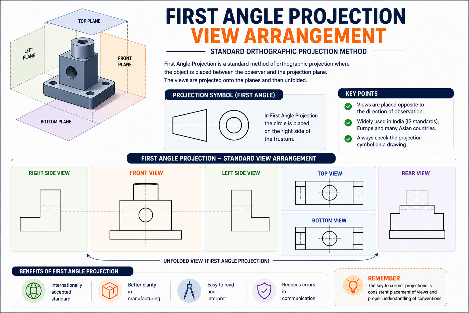
What Is 1st Angle Projection?
In First Angle Projection, the object is considered to be in the first quadrant.
The object is positioned between the observer and the projection plane.
This affects where the projected views appear on the engineering drawing.
For example:
The top view is placed below the front view.
The right-side view is placed on the left side of the front view.
The left-side view is placed on the right.
This can initially feel counterintuitive, but the arrangement follows directly from the projection method.
Easy way to remember
First Angle → views appear on the opposite side.
What Is 3rd Angle Projection?
In Third Angle Projection, the object is considered to be in the third quadrant.
Here, the projection plane lies between the observer and the object.
As a result, the views are arranged more intuitively:
The top view appears above the front view.
The right-side view appears on the right.
The left-side view appears on the left.
Easy way to remember
Third Angle → views appear on the same corresponding side.
First Angle vs Third Angle Projection
Feature
1st Angle
3rd Angle
Quadrant
First
Third
Object relationship
Object between observer and plane
Plane between observer and object
Top view
Below front view
Above front view
Right-side view
Left of front view
Right of front view
View arrangement
Opposite side
Corresponding side
Used for engineering drawings
Yes
Yes
The important point is not simply memorising where each view goes.
A design engineer should understand why the views appear there.
That understanding becomes valuable when reading production drawings, preparing CAD drawings, checking components or communicating with manufacturing teams.
Then Why Not 2nd and 4th Angle Projection?
This is where the concept becomes interesting.
Consider what happens when the reference planes are rotated or unfolded to create a two-dimensional engineering drawing.
In the second and fourth quadrant arrangements, the resulting front and top views can occupy the same region of the drawing.
In practical terms, the views can overlap, making the representation ambiguous and difficult to interpret.
Engineering drawings are meant to communicate geometry clearly.
If two different views occupy the same drawing space, that clarity is lost.
This is the fundamental reason 2nd Angle and 4th Angle Projection are not normally adopted as standard orthographic projection methods for engineering drawings.
By contrast, 1st and 3rd Angle Projection allow the principal views to be arranged clearly and consistently.
International technical-drawing standards formally define orthographic projection methods. ISO 5456-2 specifically addresses orthographic representations, while ISO 128-3:2022 specifies general principles for presenting views, sections and cuts based on those methods.
Why Does This Matter in Real Engineering?
It may look like a textbook topic.
It isn’t.
Imagine receiving a component drawing from another engineering team.
You see:
front view,
top view,
side view,
dimensions,
tolerances,
sections.
Before interpreting the geometry, you need to understand how those views have been projected.
Misreading the projection convention can lead to an incorrect understanding of the component.
That can affect:
Design → Manufacturing → Inspection → Assembly
This is why projection symbols and drawing conventions matter in professional engineering documentation.
ASME Y14.3 similarly establishes requirements for orthographic and pictorial views used on engineering drawing sheets and models.
Don’t Just Memorise the View Positions
A common way of learning engineering drawing is:
First Angle = top view below. Third Angle = top view above.
That may help in an examination.
But it doesn’t necessarily build engineering understanding.
Instead, visualize these three things:
Observer → Object → Projection Plane
Ask:
Where is the observer?
Where is the object?
Where is the projection plane?
Where will the projected view fall when the planes are unfolded?
Once that relationship becomes clear, First Angle and Third Angle Projection become much easier to understand.
Engineering Tip
Whenever you receive a production drawing, don’t assume the projection method.
Check the projection symbol and drawing convention in the title block before interpreting the views.
That small habit can prevent a large misunderstanding.
The Key Takeaway
There are four quadrants, but they don’t all produce equally practical arrangements for standard orthographic engineering drawings.
1st Angle and 3rd Angle Projection provide clear and consistent arrangements of views.
2nd and 4th Angle Projection can cause views to overlap when the projection planes are unfolded, making them unsuitable for normal engineering-drawing representation.
So the next time someone asks:
“If there are four quadrants, why do we use only 1st and 3rd Angle Projection?”
Visualize the object, observer and projection planes.
That’s where the concept starts making sense.
FAQ: 1st, 2nd, 3rd & 4th Angle Projection
Why is 2nd angle projection not used?
Second angle projection is generally not used in engineering drawings because, when the reference planes are unfolded, the front view and top view can fall in the same region of the drawing. This can create overlapping views and make the drawing difficult to interpret clearly.
Why is 4th angle projection not used?
Fourth angle projection is generally avoided for the same practical reason. After projection and unfolding of the reference planes, the principal views can overlap, which reduces clarity and can create ambiguity in technical drawings.
What is the difference between first and third angle projection?
In first angle projection, the object is positioned between the observer and the projection plane, so views are placed on the opposite side of the corresponding feature. In third angle projection, the projection plane is between the observer and the object, so views are placed on the same corresponding side.
A simple way to remember it is:
First angle: views appear on the opposite side
Third angle: views appear on the same side
Which projection method is used in engineering drawings?
Engineering drawings commonly use first angle projection and third angle projection. The method used depends on the applicable drawing standard, company practice, customer requirement, and region. The projection symbol in the title block should always be checked before interpreting the drawing.
Book a Free Demo. See What Design-Ready Training Looks Like.
Build practical mechanical design skills through domain-focused training in Plastic, Casting and Sheet Metal/BIW with live project exposure, manufacturing knowledge and mentor guidance.
Upcoming batches have limited seats. Book a free demo to understand the program structure, domain options and learning approach.
See How Domain Training Can Strengthen Your Design Career.
CAD software knowledge is only the starting point. Explore how practical training in Plastic, Casting and Sheet Metal/BIW, manufacturing processes and live projects can help you move toward design-ready skills.
Upcoming batch • Limited training seats. Book a free demo to understand the training approach before you decide.