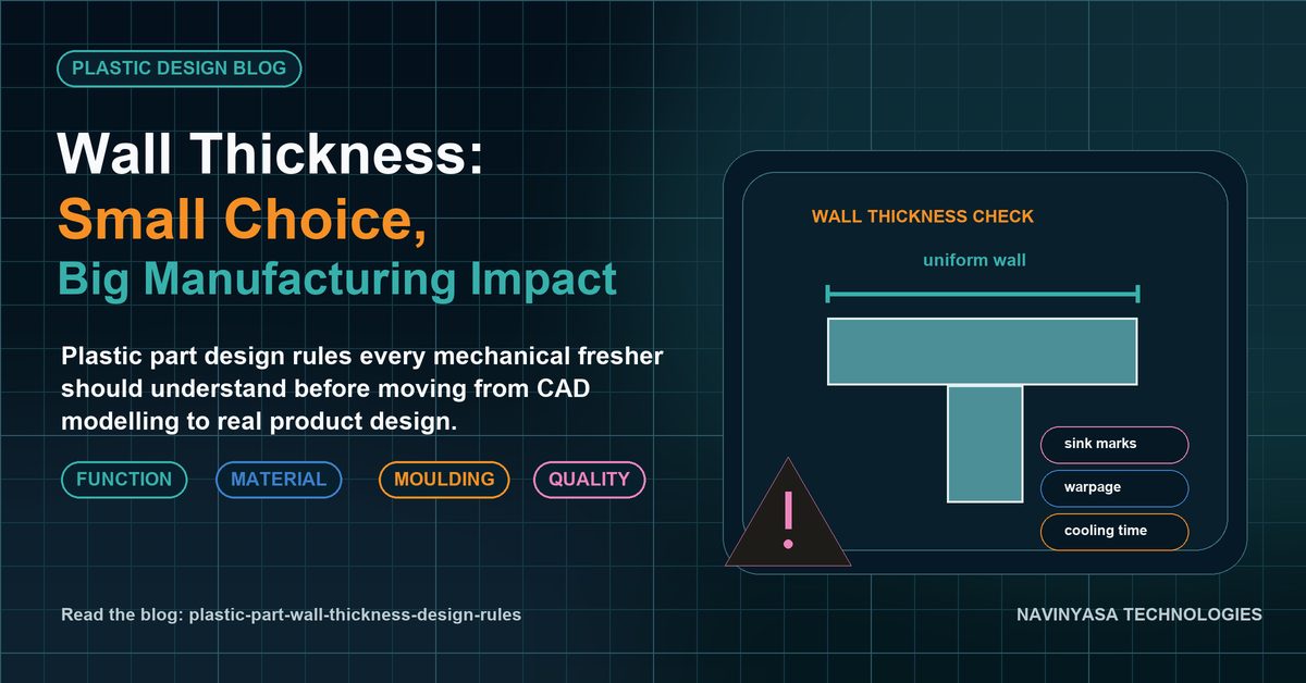
Wall thickness is one of the first design decisions that determines whether an injection-moulded plastic component will fill properly, cool predictably and retain its intended shape. A CAD model can look complete while still creating sink marks, warpage, long cycle times or unnecessary material cost if the wall strategy is wrong.
Why wall thickness matters in plastic design
Injection moulding depends on molten polymer flowing through the cavity and cooling from the mould surface inward. Thick and thin regions cool at different rates. That difference can create residual stress, visible surface defects and dimensional variation. Good plastic design therefore aims for controlled, manufacturable sections rather than simply making a part “stronger” by adding material.
10 practical wall-thickness rules
- Keep the nominal wall as uniform as practical. Consistency improves flow and cooling behaviour.
- Avoid sudden thick-to-thin transitions. Use gradual transitions so flow and shrinkage change progressively.
- Use ribs instead of thick solid sections. Ribs can add stiffness without creating a large local mass of plastic.
- Control rib thickness. Overly thick ribs can telegraph sink marks onto the cosmetic surface.
- Design bosses as supported features, not solid towers. Connect bosses using ribs or gussets where appropriate and avoid excessive mass around the base.
- Consider flow length and material behaviour. Thin walls may demand higher pressure or a different gate strategy.
- Use radii at internal corners. Sharp internal corners concentrate stress and can also affect flow.
- Think about appearance surfaces. Thick features behind Class-A or visible surfaces can create read-through or sink.
- Coordinate wall thickness with draft and tooling direction. Manufacturability decisions work together, not independently.
- Validate against the selected polymer and supplier guidelines. There is no single wall value that is correct for every resin, part size and application.
Wall thickness, ribs and bosses must be designed together
Many plastic-part defects come from local material accumulation rather than the nominal wall itself. A rib intersection, boss base or mounting feature can unintentionally create a section much thicker than the surrounding wall. During design review, evaluate the effective cross-section through these intersections, not only the value shown by a thickness-analysis tool.
Common warning signs in a CAD model
- Large solid pads added to solve stiffness issues.
- Bosses placed directly against cosmetic walls without relief.
- Sudden section changes near corners.
- Deep ribs with no draft.
- Multiple heavy features intersecting at one point.
From CAD geometry to design-ready decisions
Knowing how to create a shell command is CAD knowledge. Knowing why the wall should be uniform, how a rib changes shrinkage, and what a toolmaker may flag is design knowledge. That distinction is central to becoming design-ready.
Explore our Plastic Component Design Training or compare the broader CAD-Trained to Design-Ready pathway.
Frequently asked questions
What is the ideal wall thickness for an injection-moulded plastic part?
It depends on the polymer, flow length, geometry, structural requirement and moulding process. Start with material/supplier guidance and maintain the chosen nominal wall consistently.
Why are uniform walls preferred?
Uniform walls promote more predictable filling, cooling and shrinkage, reducing the risk of warpage, sink and internal stress.