Plastic Component Design in Mechanical Engineering: Rules, Materials and a DFM Checklist
29 Sep 2026
navinyasanew
13 min read
Pick up the nearest car key, TV remote or phone charger and look at it closely. Every curve, clip and screw post on that part was a decision someone made, usually with a toolmaker looking over their shoulder.
That is what plastic component design in mechanical engineering is really about. It is not just modelling a shape in CATIA or NX. It is designing a part that fills the mould, cools evenly, comes out cleanly and still does its job for years.
In this guide we walk through the whole picture: how to pick a material, which moulding process fits, the core design rules with real numbers, the features that trip up freshers, and a checklist you can run before any design review.
What is plastic component design?
Plastic component design is the process of turning a product requirement into a plastic part that can be made in volume, at the right cost, without defects. The CAD model is only the output. The real work is the thinking behind it.
A good plastic designer keeps three things in mind at the same time:
Function. What load, temperature, chemical or UV exposure will the part see? How long must it last?
Manufacturing. How will the tool open? Where will the plastic enter? Where will it shrink?
Assembly. How does this part meet the parts around it? Clips, screws, welding or adhesive?
Miss any one of these and the part fails somewhere: in the tool room, on the assembly line or in the customer’s hands. That is why companies treat plastic design as a domain skill and not just a software skill. We covered that gap in detail in CAD Engineer vs Design Engineer.
Start with the material, not the shape
Most design problems we see in reviews trace back to one thing: the material was picked late. The resin decides your wall thickness, draft, shrinkage, snap fit strain and even where the gate can go. So choose it early.
Plastics used in engineering parts fall into two broad families:
Amorphous (ABS, PC, PC/ABS, PMMA). Lower, more even shrinkage. Good dimensional stability and surface finish. Weaker against chemicals.
Semi-crystalline (PP, PE, PA, POM). Higher shrinkage that varies with flow direction. Better chemical and fatigue resistance. More prone to warpage if walls are uneven.
Here is a quick reference for the materials you will meet most often in automotive and consumer products.
Material
Where you will see it
Why designers pick it
Watch out for
PP / talc-filled PP (TPO blends)
Bumpers, door trims, claddings, battery trays
Low cost, light, tough, great for living hinges
High shrinkage, poor paint adhesion without treatment
ABS
Instrument panel inserts, housings, grilles
Easy to mould, good finish, easy to plate or paint
Always confirm numbers against the resin supplier’s datasheet for the exact grade. Two PP grades can behave very differently.
Choose the right moulding process
The process shapes the design rules. A rule that works in injection moulding may not apply to blow moulding at all.
Injection moulding. Molten plastic is forced into a closed steel tool under high pressure. This covers most engineering parts: trims, housings, brackets, clips. Almost every rule in this guide is written for it.
Blow moulding. Air inflates a hot plastic tube inside a mould. Used for hollow parts like fuel tanks, washer bottles and air ducts. Walls are thinner and less precise.
Compression moulding. A measured charge is pressed between heated halves. Common for SMC body panels and thermoset parts.
Extrusion. Plastic is pushed through a die to make a constant profile. Think door seals, edge trims and tubing.
Thermoforming. A heated sheet is pulled over a form. Good for large, low-volume covers and liners.
If you are new to this, focus on injection moulding first. It is where most plastic design jobs sit.
Plastic part design guidelines: the core rules
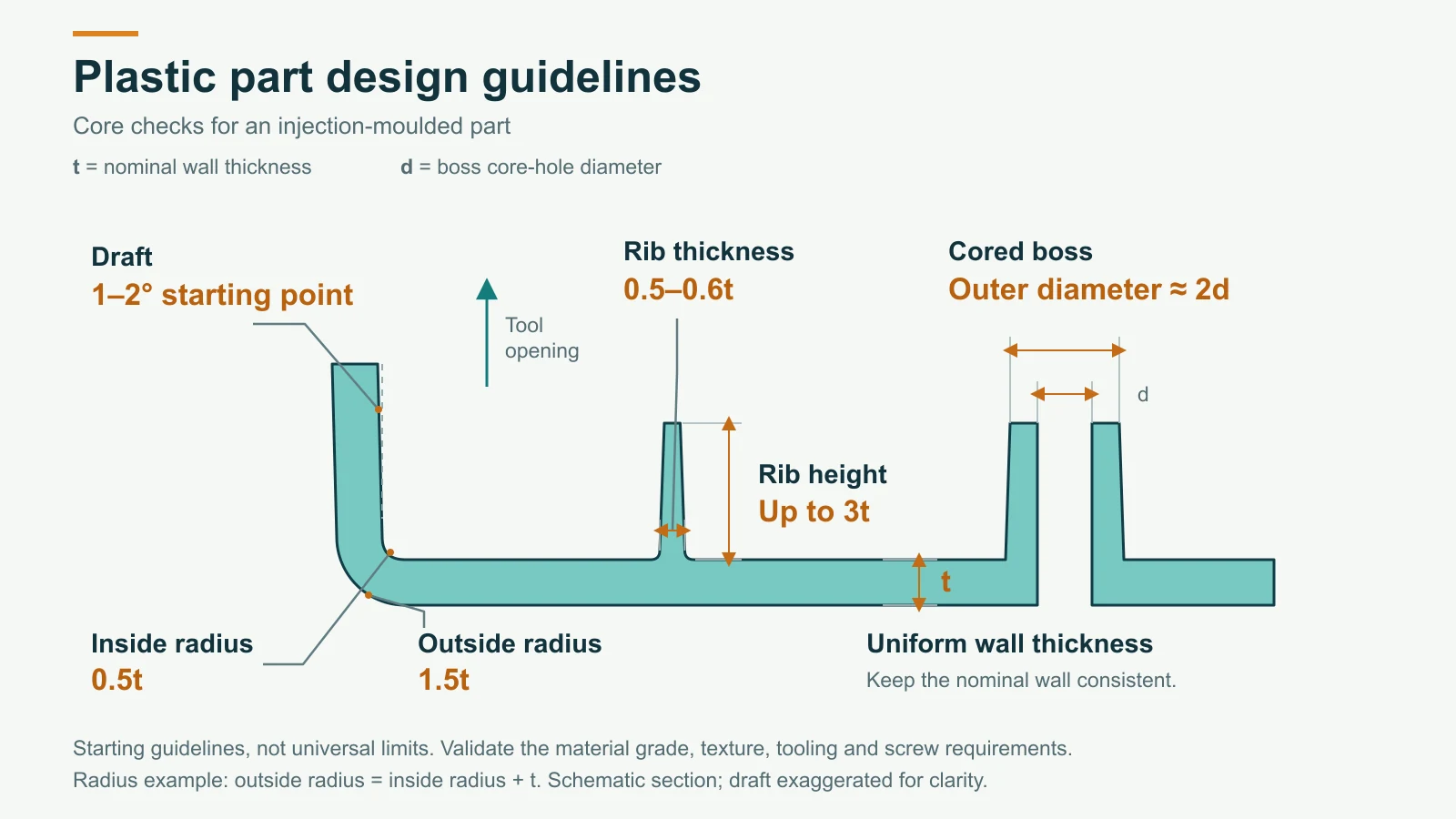
These are the rules every toolmaker expects you to know. Treat the numbers as sensible starting points, then check them against the material, part size and the supplier’s guidance. Here, t means the nominal wall thickness.
Feature
Starting rule of thumb
What goes wrong if you ignore it
Nominal wall
Keep it uniform; 1.5 to 3 mm suits most ABS, PP and PC parts
Sink marks, voids, warpage, long cycle time
Wall transitions
Blend gradually, about 3:1 length to thickness change
Stress and uneven shrinkage at the step
Draft
1 to 2 degrees on most walls; at least 0.5 degree; add about 1 degree per 0.025 mm of texture depth
Parts stick, drag marks, scuffed texture
Rib thickness
50 to 60% of t behind show surfaces; up to 70% on hidden faces
Sink marks read through to the A-surface
Rib height
Up to 3 times t
Short shots, ribs that bend or stick in the tool
Rib spacing
At least 2 times t apart
Thin steel in the tool that overheats or breaks
Boss outer diameter
About 2 times the hole diameter
Cracked bosses when screws go in
Boss wall
About 60% of t, tied back to walls with ribs or gussets
Sink marks and weak, wobbly bosses
Inside corner radius
At least 0.5 times t
Stress concentration and cracks
Outside corner radius
Inside radius plus t
Uneven wall at the corner
Hole spacing
At least 2 times t from edges and other holes
Weak webs and weld lines that crack
Blind hole depth
About 2 to 4 times the core pin diameter
Core pins that deflect or break
Wall thickness
Uniform walls are the foundation of good plastic design. Thick sections cool slowly and pull inward, leaving sink marks and voids. Thin sections next to thick ones cool faster, locking stress into the part. If you need more strength, add ribs instead of thickening the wall. Our full breakdown is in Plastic Part Wall Thickness: 10 Design Rules.
Draft angle
Plastic shrinks onto the core as it cools, so every face parallel to the tool opening needs a taper. Textured surfaces need more, because the texture grips the steel. Deep features and ribs need more too. For the full logic, including shut-offs and tooling direction, read Draft Angle Rules Every Plastic Part Designer Should Know.
Ribs
Ribs give you stiffness without the mass of a thick wall. Several thin ribs beat one fat rib every time. Give each rib draft on both faces and a small root radius, about 25 to 50% of t. Where ribs cross, the intersection gets thick, so core it out or offset the ribs.
Bosses and gussets
Bosses hold screws, inserts and locating pins. Never let a boss merge into a wall as one solid lump. Keep it slightly away from the wall and connect it with a rib, or core it from the back. Tall bosses need gussets. For self-tapping screws, always follow the screw maker’s hole size for your resin.
Radii and fillets
Sharp inside corners concentrate stress and block flow. The inside and outside radius rule above keeps the wall thickness even around the bend, which is exactly what you want.
Holes
Holes in the direction of tool opening are cheap. Holes at an angle need side actions, which add cost and maintenance. Plastic flowing around a core pin also leaves a weld line on the far side, so keep holes away from high-stress areas.
Features that make or break the part
Once the basic rules are in place, a handful of features decide whether the part is easy to tool and assemble, or a constant headache.
Snap fits
Snap fits let parts click together without screws. That saves assembly time and cost, which is why you see them all over interior trims. The key number is strain. As the hook deflects, the plastic stretches, and every material has a limit. Go past it and the hook cracks on the first assembly or slowly loses its grip.
A few habits that help:
Taper the cantilever so it gets thinner towards the tip. Strain spreads more evenly.
Put a generous radius at the root. That is where hooks break.
Use a gentle lead-in angle for insertion and a steeper return angle for retention.
Check that the hook can be moulded without a side action. If not, add a window in the wall below it.
Living hinges
A living hinge is a thin flexible strip that joins two rigid sections, like the lid on a shampoo cap. PP is the go-to material because it survives huge numbers of flex cycles. Hinge sections are typically around 0.2 to 0.5 mm thick, and the gate should push plastic across the hinge, not along it.
Undercuts
An undercut is any feature that stops the part from coming straight out of the tool. Side holes, hooks and inward lips are common examples. Each one needs a slider, lifter or collapsible core, and each adds cost, cycle time and a new place for flash. Before accepting an undercut, ask: can this feature be redesigned so the tool opens in a straight pull?
Gates and parting lines
The gate is where plastic enters the cavity. The parting line is where the two tool halves meet. Neither is only the toolmaker’s problem. The gate affects weld lines, fibre direction, warpage and where the gate mark shows. The parting line affects draft direction and where a witness line appears on the part.
Good practice is to gate into the thicker sections, keep gates off cosmetic faces, and push weld lines to low-stress, hidden areas. Agree on both with the tool designer early, ideally before detailing starts.
Shrinkage and warpage
Every plastic shrinks as it cools, and the tool is cut oversize to allow for it. Amorphous resins like ABS and PC usually shrink around 0.4 to 0.7%. Semi-crystalline resins like PP and PA can shrink 1 to 2.5% or more, and glass-filled grades shrink differently along and across the flow.
Warpage happens when shrinkage is uneven. The usual causes are uneven walls, poor gate location and unbalanced cooling. Uniform walls and a mould flow check before tool release catch most of it.
Why metal thinking fails for plastic strength
Mechanical engineers are trained on steel and aluminium. So it feels natural to run a stress check, compare Von Mises stress with yield strength and call it done. With plastics, that can mislead you.
Plastics react differently to tension and compression, and they are sensitive to hydrostatic stress. A study in Materials & Design by Mascarenhas, Ahrens and Ogliari (2004) makes this point clearly: the Von Mises criterion used for metals can lead to over- or under-designed plastic parts, and pressure-dependent criteria such as modified Von Mises or Drucker-Prager are a better fit.
On top of that, plastics creep under constant load, lose stiffness as temperature rises and can weaken with moisture or UV. In practice this means:
Use material data at the real operating temperature, not room temperature.
Allow for long-term load, not just short-term strength.
Apply sensible safety factors, especially near weld lines, where strength can drop noticeably.
For glass-filled parts, remember that stiffness depends on fibre direction, which mould flow can predict.
The plastic component design workflow
Here is how a plastic part typically moves from brief to production in an automotive or product design team.
Understand the requirement. Loads, temperature range, fitment, appearance class, target weight and cost.
Pick the material and process. Shortlist grades and check datasheets for shrinkage, stiffness and heat resistance.
Define tooling direction and parting line. Decide how the tool opens before you model details.
Build the concept. Set the nominal wall and main surfaces. For styled parts, this is where Class-A surfaces come in.
Add features. Ribs, bosses, clips, locators and snap fits, all following the rules above.
Run checks. Draft analysis and thickness analysis in CATIA, NX or Creo, plus a basic stiffness check.
Do a mould flow study. Check fill, weld lines, air traps, sink and warpage. Adjust gate and walls if needed.
Hold a tooling feasibility review. Walk the toolmaker through undercuts, sliders, lifters and shut-offs.
Prototype and validate. 3D print or soft tool the part and test fit, function and assembly.
Release the design. Final 2D drawing with GD&T, material callout and appearance zones.
Common mistakes freshers make
These come up again and again in portfolio reviews and interview tests:
Solving stiffness with thickness. A thicker wall adds weight, cycle time and sink marks. Ribs almost always do the job better.
Forgetting draft until the end. Adding draft to a finished model breaks features and mating faces. Build it in from the start.
Bosses fused to walls. Creates a thick lump right behind the show surface.
Sharp inside corners everywhere. They look clean in CAD but crack in real life.
Ignoring the tool opening direction. Features get modelled that simply cannot come out of a straight-pull tool.
Copying numbers without context. A rib ratio that works for ABS may cause sink on a glossy PC part.
Treating the part alone. Plastic parts live in assemblies. Gaps, flush and tolerance stack-ups matter as much as the part itself.
Plastic part DFM checklist
Run through this before every design review. It takes ten minutes and saves weeks of tool rework.
Material grade chosen and datasheet checked for shrinkage, heat and stiffness
Tool opening direction and parting line agreed
Nominal wall uniform, with gradual transitions
Draft on every face parallel to tool opening, extra draft on textured faces
Ribs 50 to 60% of wall behind show surfaces, height within 3 times wall
Bosses cored, tied back with ribs or gussets, sized to the screw maker’s guide
Inside radii at least half the wall, outside radii equal to inside plus wall
Undercuts removed or justified, with slider or lifter space checked
Gate location and weld lines agreed with the tool designer
Draft and thickness analysis run in CAD
Mould flow checked for fill, sink, air traps and warpage
Snap fit strain within the material limit
Assembly clearances and tolerance stack-up verified
Drawing complete with GD&T, material callout and appearance zones
Frequently asked questions
What is plastic component design in mechanical engineering?
It is the design of plastic parts that work well and can be made in volume, usually by injection moulding. It combines product requirements, material knowledge, moulding rules and assembly needs into one CAD model and drawing.
What is the ideal wall thickness for a plastic part?
There is no single number. Many ABS, PP and PC parts sit between 1.5 and 3 mm, but the right value depends on the resin, part size, flow length and load. What matters most is keeping the wall uniform.
What is the rule for rib thickness?
A common starting point is 50 to 60% of the nominal wall behind visible surfaces, and up to about 70% on hidden faces. Rib height is usually kept within 3 times the wall.
How much draft angle does a plastic part need?
Around 1 to 2 degrees works for most walls, with 0.5 degree as a practical minimum. Textured surfaces need more, roughly 1 extra degree for every 0.025 mm of texture depth.
Which software is used for plastic part design?
CATIA V5 and 3DEXPERIENCE, Siemens NX, Creo and SolidWorks are the most common. Automotive OEMs and suppliers in India lean heavily on CATIA and NX. Mould flow tools such as Moldflow are used for filling and warpage studies.
What is the difference between plastic part design and mould design?
The part designer defines the product: shape, walls, features and material. The mould or tool designer designs the steel tool that makes it: cavity, core, sliders, cooling and ejection. The two work closely, and a part designer who understands tooling is far more valuable.
Is plastic design a good career for mechanical engineers?
Knowing the rules is step one. Applying them on real parts, defending your choices in a design review and explaining them in an interview is what gets you hired.
Navinyasa’s Plastic Component Design Training in Bengaluru covers materials, moulding processes, automotive interior and exterior parts, and all the design rules in this guide, with live projects and mentor guidance from engineers who work on these parts every day.
Book a free demo or WhatsApp us at +91 990 113 6476 to see what the program looks like.
Book a Free Demo. See What Design-Ready Training Looks Like.
Build practical mechanical design skills through domain-focused training in Plastic, Casting and Sheet Metal/BIW with live project exposure, manufacturing knowledge and mentor guidance.
Upcoming batches have limited seats. Book a free demo to understand the program structure, domain options and learning approach.
See How Domain Training Can Strengthen Your Design Career.
CAD software knowledge is only the starting point. Explore how practical training in Plastic, Casting and Sheet Metal/BIW, manufacturing processes and live projects can help you move toward design-ready skills.
Upcoming batch • Limited training seats. Book a free demo to understand the training approach before you decide.