Parting Line in Casting: How to Choose It, With Rules, Tolerances and a Worked Example
20 Oct 2026
navinyasanew
10 min read
Every casting is made in a mould that has to open. Where it opens is the parting line, and it is usually the first real decision in casting design. It sets which way the draft runs, how many cores you need, where the flash ends up, and which dimensions get looser tolerances.
Last week we covered draft angle in casting, and the first rule there was to settle the parting line before adding a single degree of draft. This post covers that step: what a parting line is, the main types, how to choose one, and what it does to your tolerances, with a worked example you can follow.
What is a parting line in casting?
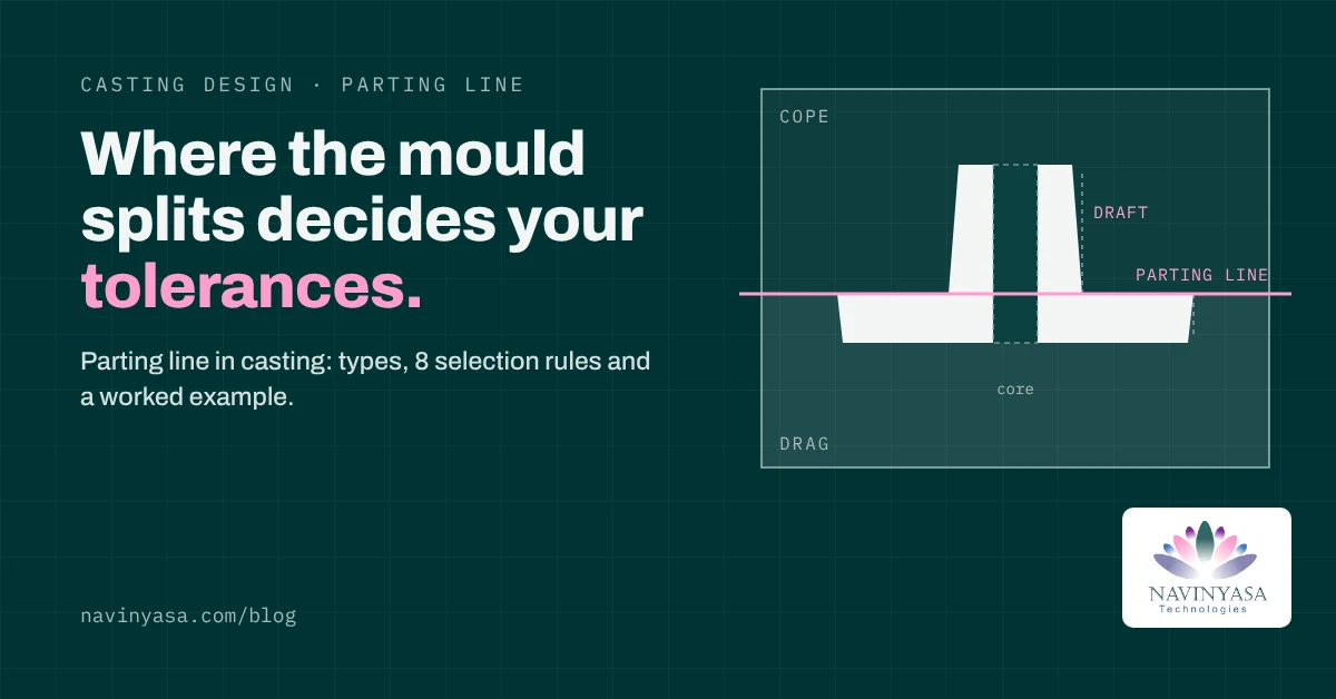
The parting line is the line on a casting where the two halves of the mould met. The mating faces of the two halves are called the parting surface. The thin seam, or witness line, those faces leave on the finished part is the parting line.
The names change with the process, but the idea stays the same:
Sand casting: the top half of the mould box is the cope and the bottom half is the drag. The pattern is split, or placed, so that each half can be lifted off without breaking the sand.
Die casting and gravity die casting: the two steel halves are the cover die (fixed) and the ejector die (moving). The part stays on the ejector side and ejector pins push it out.
Investment casting: the wax pattern is made in a split die, so the parting line matters there too, even though the final ceramic shell has no joint.
Why the parting line matters so much
A parting line looks like a thin seam on a drawing. In practice it drives most of what happens next:
Draft direction. Draft always runs away from the parting line, in the direction each half moves.
Cores and side actions. A badly placed parting line creates undercuts, and every undercut needs a core in sand casting or a slide in die casting.
Flash. Metal can squeeze into the joint between the two halves, leaving a thin fin that has to be ground or trimmed off.
Mismatch. If one half shifts slightly against the other, the casting shows a small step at the parting line. Foundries call this shift or mismatch.
Tolerances. A dimension that crosses the parting line is looser than the same dimension kept inside one half, because the joint itself adds variation.
Cost. An offset parting line can mean a more expensive pattern, an extra core or more fettling time on every part.
Types of parting line
Most castings use one of four types.
Type
What it looks like
When it is used
Watch out for
Straight (flat)
One flat plane through the part
Most parts, whenever the shape allows it
Nothing major; this is the default to aim for
Stepped (offset)
Two or more flat levels joined by a step
Parts with features at different heights
Costlier patterns, fins at the steps, more risk of swell in sand
Curved (contoured)
Follows the curve of the part
Curved housings, levers, crankshaft-like parts
Harder to make and fit, harder to keep flash tight
Split with side cores or slides
A main parting line plus extra moving parts
Side holes, pockets and undercuts that cannot come out straight
Every extra joint adds its own flash line and tolerance
The industry rule of thumb is simple. A straight parting line is almost always the best choice, and it is often worth changing the part slightly to get one.
How to choose a parting line: 8 rules
Work through these in order. Not every rule can win on every part, so the job is to find the best balance and agree it with the foundry or die caster early.
Keep it straight. A flat parting line gives the cheapest pattern or die, the least flash and the fewest surprises.
Put it at the largest cross-section. Splitting the part where it is widest lets both halves draw away cleanly without undercuts.
Keep as much of the casting as possible in one half. In sand casting that is usually the drag. Features that sit in the same half cannot shift against each other, so mismatch is no longer a problem for them.
Put the most detailed face in the drag. In sand casting, the drag fills better, and non-metallic inclusions tend to float up to the top of the casting.
Design out cores where you can. Choose the orientation that needs the fewest cores. Each core adds cost, a core print and another chance of core shift.
Keep critical dimensions inside one half. Dimensions that cross the parting line get extra tolerance. More on this below.
Keep it off surfaces that matter. Avoid machined faces, sealing faces and visible cosmetic surfaces, because flash and the witness line land right on the parting line.
Put all machining locators in one half. If datums sit on both sides of the parting line, any cope-to-drag shift moves them apart and the part loads badly on the machine. Keep them together, ideally in the drag.
Worked example: a flanged hub
Take a simple sand-cast hub: a flange 120 mm in diameter and 15 mm thick, with a hub 60 mm in diameter rising 70 mm above it and a 30 mm bore through the middle. The hub has to run true to the flange. Here are three ways to split it.
Option
How it is split
What works
What hurts
A: axis vertical, parting at the flange’s top face
Flange in the drag, hub in the cope
Straight line at the largest section; flange faces need no draft
Hub-to-flange alignment now crosses the parting line, so any shift shows as a step at the hub root
B: axis vertical, parting at the top of the hub
Whole casting in the drag
Straight line; flange and hub sit in one half, so they cannot shift against each other
A deep drag cavity (85 mm) with draft along the full height of the hub
C: axis horizontal, parting through the centre line
Each half holds half of every diameter
The bore core sits neatly in core prints in both halves
Every round surface crosses the parting line, and the flange faces now run along the draw, so they need draft
If the hub-to-flange alignment is the critical requirement, Option B usually wins. Option A becomes the better choice when the hub is tall enough that the deep drag cavity gets awkward to mould. Option C is rarely the best answer for this part. The point is not the answer itself. It is that each option trades off draft, cores, mismatch and tolerance in a different way, and you should see those trade-offs before you model the details.
Tolerances across the parting line
This is the part most students never hear about. When two mould or die halves close, they never meet perfectly. There is always a little gap, a little shift, or both. So a dimension that runs from one half to the other picks up extra variation that a dimension inside one half does not.
Die casting: the NADCA rule
The North American Die Casting Association (NADCA) handles this with a simple rule. For any dimension across the parting line:
T_{total} = T_{linear} + T_{parting\ line}
The parting line tolerance is plus only, because the halves can be held slightly apart but never pushed closer than fully closed. It grows with the projected area of the casting, which is the area you see when you look at the part straight down the direction the die opens.
Projected area
Aluminium
Zinc
Magnesium
Up to 64.5 cm² (10 in²)
+0.14 mm
+0.114 mm
+0.14 mm
71 to 129 cm² (11 to 20 in²)
+0.165 mm
+0.13 mm
+0.165 mm
135.5 to 322.6 cm² (21 to 50 in²)
+0.19 mm
+0.15 mm
+0.19 mm
329 to 645.2 cm² (51 to 100 in²)
+0.30 mm
+0.23 mm
+0.30 mm
651.6 to 1290.3 cm² (101 to 200 in²)
+0.46 mm
+0.30 mm
+0.46 mm
1296.8 to 1935.5 cm² (201 to 300 in²)
+0.61 mm
+0.46 mm
+0.61 mm
These are NADCA standard values, added to the linear tolerance. For larger parts, NADCA says to consult your die caster. Slides and moving cores follow a similar idea, with their own plus-only tolerance.
Worked example: one dimension, two placements
An aluminium die-cast housing has a projected area of about 100 cm². You need to hold a 76.2 mm (3 in) height.
NADCA’s standard linear tolerance for aluminium is ±0.25 mm for the first 25.4 mm, plus ±0.025 mm for each additional 25.4 mm. For 76.2 mm that is ±0.25 + 2 × 0.025 = ±0.30 mm.
If the height sits inside one die half: the tolerance stays at ±0.30 mm.
If the height crosses the parting line: add +0.165 mm for the 71 to 129 cm² band. The tolerance becomes +0.465 / −0.30 mm.
Same part, same machine, but 0.165 mm extra on one side simply because of where the die splits. If that height is critical, move it into one half or plan to machine it.
Sand casting: mismatch and flash
Sand moulds are less rigid than steel dies, so shift is a bigger factor. One common design guide suggests planning for parting line mismatch of up to about 0.5 mm (0.020 in), and seam flash of up to about 0.4 mm (0.015 in). Treat these as planning figures, not a standard. Real values depend on the foundry, the moulding method and the part size. ISO 8062-3 treats surface mismatch separately from the general dimensional tolerances, so ask your foundry which tolerance grade they quote and how they handle mismatch.
Common parting line mistakes in student casting models
These show up again and again in the casting projects we review during training:
Modelling first, choosing the parting line last. By then the draft, ribs and bosses all point the wrong way.
Not showing the parting line on the drawing. The foundry has to guess, and the guess may not match your tolerances.
Splitting a critical pair of features. A bearing seat and its mounting face on opposite halves will never line up as well as the drawing suggests.
Stepping the parting line to save a core, without checking the cost. An offset line can need a more expensive matchplate pattern and leave fins at every step.
Leaving flash on a sealing face. Gaskets and O-rings do not like a seam running across them.
Datums on both sides. The machinist clamps on one half and measures from the other, and the shift shows up as scrap.
Parting line checklist
Run through this before you add draft or detailed features:
Parting line chosen and drawn on the model and the drawing
Straight, unless there is a clear reason it cannot be
At or near the largest cross-section
As much of the part as possible in one half (the drag, for sand casting)
Cores and slides kept to the minimum
Critical and tight-tolerance dimensions kept inside one half
Off machined, sealing and cosmetic surfaces
Machining datums all in one half
Cross-parting-line tolerances checked (NADCA for die casting, the foundry’s grade for sand)
Draft direction set from the parting line
Agreed with the foundry or die caster before detailing
Frequently asked questions
Why are dimensions across the parting line less accurate?
Because the two halves never close perfectly. NADCA adds a plus-only parting line tolerance, from +0.114 mm upwards depending on alloy and projected area, to any die-cast dimension that crosses the joint.
What is mismatch in casting?
Mismatch, or shift, is when one half of the mould moves slightly against the other. It shows up as a small step on the casting at the parting line.
Is the parting line the same in casting and plastic moulding?
The idea is the same: the line where the tool halves meet. The numbers differ, because metal shrinks differently and sand moulds behave nothing like steel injection tools. Our plastic component design guide covers the plastic side.
Learn casting design the way the shop floor sees it
A parting line is easy to draw and hard to choose well. That judgement comes from seeing real castings, real patterns and real rejections, not from CAD commands alone.
Navinyasa’s Casting Component Design Training in Bengaluru covers casting materials, sand, die, gravity and investment casting, tool direction, parting line identification and draft, with live projects and mentor guidance. Book a free demo or WhatsApp us at +91 990 113 6476.
Book a Free Demo. See What Design-Ready Training Looks Like.
Build practical mechanical design skills through domain-focused training in Plastic, Casting and Sheet Metal/BIW with live project exposure, manufacturing knowledge and mentor guidance.
Upcoming batches have limited seats. Book a free demo to understand the program structure, domain options and learning approach.
See How Domain Training Can Strengthen Your Design Career.
CAD software knowledge is only the starting point. Explore how practical training in Plastic, Casting and Sheet Metal/BIW, manufacturing processes and live projects can help you move toward design-ready skills.
Upcoming batch • Limited training seats. Book a free demo to understand the training approach before you decide.