Snap Fit Design for Plastic Parts: Cantilever Formula, Strain Limits and a Worked Example
27 Oct 2026
navinyasanew
10 min read
Open the battery cover on a TV remote. Press the clip on a car door trim panel. Click a phone case into place. Each time, a small plastic hook bends, slides over a lip and springs back. No screws, no glue, no extra parts.
That hook is a snap fit, and it is one of the most useful features a plastic designer can draw. It is also one of the easiest to get wrong. Make it too stiff and it cracks the first time someone assembles it. Make it too soft and the part rattles loose in a year.
This guide covers the three main types of snap fit, the cantilever formula that tells you how far a hook can safely bend, real strain limits for common plastics, the design rules toolmakers expect, and a worked example you can copy.
What is a snap fit?
A snap fit is a joint in which a flexible feature on one part deflects during assembly, passes over a mating feature, and then springs back to lock the two parts together. The flexing feature does the work of a screw or clip, but it is moulded into the part itself.
That is why snap fits are everywhere in plastic products. They cut part count, speed up assembly and remove the cost of fasteners. They work best when the design keeps the plastic within its elastic limit, so it springs back instead of cracking or creeping.
Types of snap fit
Type
How it works
Where you see it
Notes
Cantilever
A beam with a hook at the end bends sideways and snaps behind a ledge
Battery covers, trim clips, housings, enclosures
The most common type, and the easiest to calculate
Annular
A ring-shaped bead on one part expands or squeezes over a groove on the other
Pen caps, bottle closures, ball sockets
Hard to predict by hand, because the whole ring deforms
Torsional
A bar twists instead of bending, often with a lever to release it
Push-release latches, lids, ratchets
Good for joints that are opened often
This post focuses on the cantilever snap fit, because it is the one you will draw most often and the one design reviews ask about first. Variants such as U-shaped and L-shaped clips follow the same logic, with a longer effective beam.
How a cantilever snap fit works
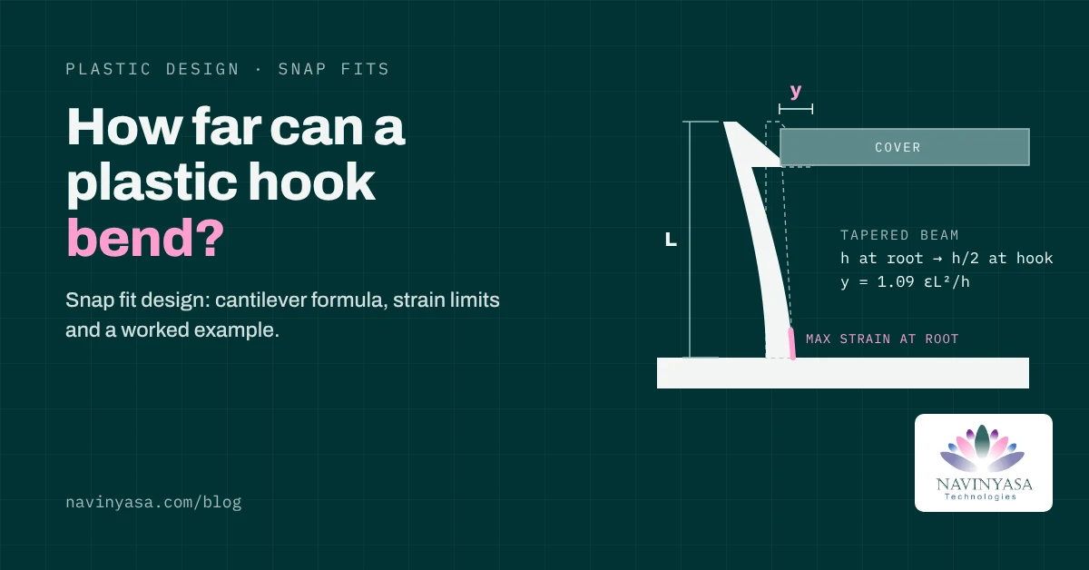
During assembly, the hook is pushed sideways by the height of the undercut, y. That bending stretches the plastic on one face of the beam, with the most strain at the root, where the beam meets the wall. If that strain stays under the material’s limit, the hook springs back. If it goes over, the hook cracks or takes a permanent set.
So the real design question is simple: how far can this beam bend before the strain at the root gets too high?
The cantilever formula
For a beam of constant rectangular section on a rigid wall, the allowable deflection is:
y = 0.67 \times \frac{\varepsilon \, L^{2}}{h}
If the beam tapers so that its thickness at the hook is half its thickness at the root, the same strain allows much more deflection:
y = 1.09 \times \frac{\varepsilon \, L^{2}}{h}
Where y is the allowable deflection (the undercut height), ε is the permissible strain as a decimal (2.5% = 0.025), L is the beam length from root to hook, and h is the beam thickness at the root.
Two things jump out of this formula. Deflection grows with the square of the length, so a slightly longer beam helps a lot. And it shrinks as thickness grows, so a thicker beam is not a stronger snap fit; it is a stiffer one that cracks sooner.
Permissible strain: how much can the plastic take?
The permissible strain depends on the material and on how often the joint is used. Bayer’s snap-fit design guide gives these short-term values for a joint assembled once, at 23 °C:
Material
Permissible strain, single assembly
Frequent separation (about 60%)
Polycarbonate (PC)
4%
2.4%
PC blends
3.5%
2.1%
PC/ABS
2.5%
1.5%
PC with 10% glass fibre
2.2%
1.3%
PC with 20% glass fibre
2.0%
1.2%
For a joint that is opened and closed often, the guide recommends using about 60% of the single-assembly value. Glass-filled grades are much stiffer and less forgiving, so their limits drop quickly.
For other resins, such as ABS, PA, POM or PP, always take the permissible strain from the resin supplier’s snap-fit data for the exact grade. Nylon in particular changes a lot between dry and moisture-conditioned states.
The forces: deflection and assembly
The force needed to bend the hook to that deflection is:
P = \frac{b \, h^{2} \, E \, \varepsilon}{6 \, L}
The push-on force the assembler actually feels depends on the lead angle α and the friction coefficient μ between the two parts:
W = P \times \frac{\mu + \tan\alpha}{1 - \mu \tan\alpha}
Here b is the beam width and E is the material’s secant modulus at that strain. The same equation with the return angle in place of the lead angle gives the pull-off force, which is how strongly the joint holds.
Snap fit design guidelines
These are the rules a toolmaker or senior designer will check in a review. Treat the numbers as starting points and confirm them against the resin supplier’s data.
Feature
Starting rule
Why it matters
Beam taper
Thin the beam from h at the root to about h/2 at the hook
Spreads the strain along the beam and allows about 60% more deflection
Beam length
Aim for a length of about 10 times the root thickness where space allows
Below about 10:1, the simple formula underestimates the strain, so short beams need a correction factor or FEA
Root radius
About half the wall thickness, and never below 0.38 mm (0.015 in)
The root is where hooks crack; a sharp corner multiplies the stress
Wall behind the root
Keep the local section close to the nominal wall
Too big a fillet makes a thick spot that causes sink marks and voids
Lead (insertion) angle
25 to 35 degrees is a common starting range
A steeper angle raises the push-on force sharply
Return (retention) angle
Below 90 degrees if it must come apart; 90 degrees for a permanent joint
A 90 degree face cannot be released without a tool or window
Hook depth
Equal to the allowable deflection y from the formula, minus tolerance
Too deep and it overstrains; too shallow and it pops out
Draft
Draft the beam faces along the line of draw like any other wall
Without it the hook drags and scuffs on ejection
Moulding the hook: avoid the side action if you can
A hook that faces sideways is an undercut, and an undercut normally needs a slider or lifter in the tool. That adds cost and maintenance. Two common ways around it:
A window under the hook. Cut a through-opening in the wall directly below the hook, so a core can pass straight through and form the hook face in a straight pull.
Hook at the edge of the part. Place the hook where its underside can be formed by the parting line.
If neither works, plan for a lifter early, and check that there is room for it to travel. Our draft angle guide for plastic parts covers how tooling direction drives these decisions.
Pick the material for the job
Tough, ductile resins such as PC, PC/ABS and PP forgive more strain. Glass-filled grades are stiff and strong but brittle at the root, so they suit short-deflection, high-force latches, not soft clips. If the joint will be opened often, check fatigue and creep data as well as the one-time strain limit, and remember that the hook should sit unstressed once it is assembled.
Worked example: a PC/ABS cover clip
Say you are designing a cantilever clip to hold a cover on a PC/ABS electronics housing. Space allows a beam 15 mm long, 6 mm wide and 1.5 mm thick at the root. The cover will be opened for servicing now and then.
Step 1: pick the permissible strain. PC/ABS allows 2.5% for a single assembly. Because the cover will be opened again, use about 60% of that: 1.5%.
Step 2: find the allowable deflection. With a constant-section beam:
Single assembly: y = 0.67 × 0.025 × 15² / 1.5 = 2.51 mm
Frequent opening: y = 0.67 × 0.015 × 15² / 1.5 = 1.51 mm
If you taper the beam to 0.75 mm at the hook, the frequent-opening limit rises to 1.09 × 0.015 × 15² / 1.5 = 2.45 mm. That is the difference between a hook that barely holds and one with a comfortable undercut.
Step 3: check the forces. Using an illustrative secant modulus of 2,000 MPa (take the real value from your grade’s datasheet) at the single-assembly strain:
Deflection force: P = 6 × 1.5² × 2,000 × 0.025 / (6 × 15) = 7.5 N
Push-on force with a 30 degree lead angle and μ = 0.5: W = 7.5 × 1.515 = 11.4 N
Pull-off force with a 45 degree return angle: W = 7.5 × 3.0 = 22.5 N
Design choice
Allowable undercut
What it means
Straight beam, single assembly
2.51 mm
Fine for a clip that is assembled once
Straight beam, frequent opening
1.51 mm
Shallow hook, may pop out under vibration
Tapered beam, frequent opening
2.45 mm
Same strain, a much more secure hook
The pull-off force is about twice the push-on force, so the cover goes on easily but resists coming off. That is usually what you want. If service technicians struggle to open it, lower the return angle a little rather than thinning the beam.
Common snap fit mistakes
These are the ones we see most often in student and early-career plastic designs:
Making the beam thicker to make it “stronger”. It gets stiffer, the root strain shoots up, and it cracks on first assembly.
A sharp corner at the root. This is the single most common cause of snap fit failure.
Designing the hook from a picture, not a calculation. A quick strain check takes five minutes and saves a tool modification.
Using the single-assembly strain for a joint that is opened every week. Use about 60% of the value for frequent separation.
Forgetting the undercut needs tooling. A sideways hook with no window or lifter plan will come back from the toolmaker with a question mark.
Leaving the hook under load after assembly. Plastics creep, so a hook that is always bent slowly relaxes and the joint loosens.
Ignoring tolerances. If the mating parts can be 0.3 mm apart, a 0.5 mm hook may only engage by 0.2 mm in the worst case.
Snap fit design checklist
Snap fit type chosen: cantilever, annular or torsional
Material and grade confirmed, with its permissible strain from the supplier
Strain limit reduced to about 60% if the joint will be opened often
Allowable deflection calculated, and the hook depth set from it
Beam tapered towards the hook where space allows
Beam length about 10 times the root thickness, or a correction applied
Root radius about half the wall, and at least 0.38 mm
Lead and return angles chosen for the assembly and removal forces you want
Undercut formed by a window, parting line or planned lifter
Draft added along the line of draw
Hook unstressed once assembled
Worst-case tolerance stack checked for engagement
Prototype tested for assembly, removal and repeated use
Frequently asked questions
What is a snap fit in plastic design?
A snap fit is a joint where a flexible moulded feature bends during assembly, passes over a mating feature and springs back to lock two parts together, with no screws or adhesive.
What are the types of snap fit?
The three main types are cantilever, annular and torsional. Cantilever snap fits are the most common and the easiest to calculate.
How do you calculate a cantilever snap fit?
For a constant-section beam, the allowable deflection is y = 0.67 × ε × L² / h. For a beam tapered to half thickness at the hook, use 1.09 instead of 0.67. Then check the push-on and pull-off forces with the mating force equation.
What strain is allowed in a snap fit?
It depends on the material. Bayer’s design guide gives 4% for polycarbonate and 2.5% for PC/ABS for a single assembly, and about 60% of that for joints opened often. Use the supplier’s data for your exact grade.
Why do snap fits break?
Usually because the strain at the root is too high. The common causes are a sharp root corner, a beam that is too thick or too short, or a hook that is deeper than the material can bend.
Can a snap fit be moulded without a side action?
Often, yes. A window cut through the wall under the hook lets a core form the hook face in a straight pull, so no slider or lifter is needed.
Design plastic parts that assemble right the first time
The formula gets you a safe hook. Knowing where to put it, how the tool will form it and how it behaves after a year in a hot car is what makes you a design engineer.
Navinyasa’s Plastic Component Design Training in Bengaluru covers plastic materials, moulding processes, wall thickness, ribs, bosses, draft and snap fits on real automotive interior and exterior parts, with live projects and mentor guidance. Start with our plastic component design guide, then book a free demo or WhatsApp us at +91 990 113 6476.
Book a Free Demo. See What Design-Ready Training Looks Like.
Build practical mechanical design skills through domain-focused training in Plastic, Casting and Sheet Metal/BIW with live project exposure, manufacturing knowledge and mentor guidance.
Upcoming batches have limited seats. Book a free demo to understand the program structure, domain options and learning approach.
See How Domain Training Can Strengthen Your Design Career.
CAD software knowledge is only the starting point. Explore how practical training in Plastic, Casting and Sheet Metal/BIW, manufacturing processes and live projects can help you move toward design-ready skills.
Upcoming batch • Limited training seats. Book a free demo to understand the training approach before you decide.